

Home /MI-T-50K-AG-N-HHHHHHHHH
| Input Voltage AC (sine wave) | 415 V±10% L-L, 50 Hz, 3-phase, 4 wire, P.F >=0.90 |
| Distortion Factor | 3.5% max (Active Power factor Correction) |
| Input Overvoltage | The input over voltage trip works above 540VAC, recycled to restore by GUI application Master On /Off button after fault removal. |
| Input Undervoltage | The input under voltage trip works below 330VAC, recycled to restore by GUI application Master On /Off button after fault removal. |
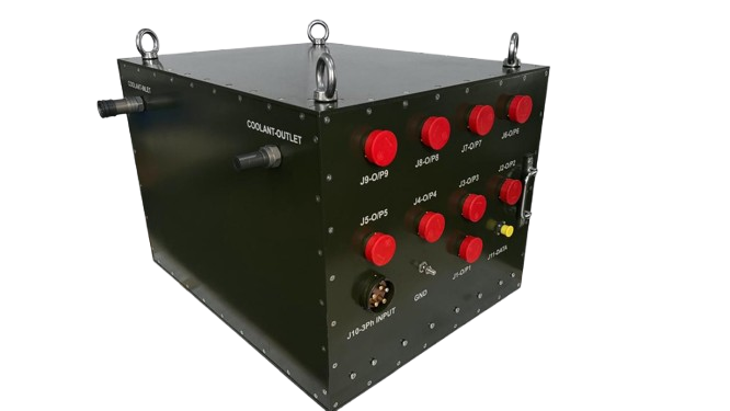
| Power Input | 1x RGMR03050M40BWR (Allied Conn, 5 Contacts, Contact Size 0 box mounting type Receptacle Male) (Mating Connector RGMFM06050F40BWR + back shell is Vendor scope) |
| Power Output 1-8 | 1- 8 MGR 00M 28-15S B051 C30 101E SQGBM (Allied Conn, 35 Contacts, Contact Size 16 Wall mounting type Recptacle female (Mating MGR 06M 28-15P C30 101+ back shell is vendor scope) |
| Power Output 9 | MGR 00M 28-15S B051 C30 101E SQGBM (Allied Conn, 35 Contacts, Contact Size 16 Wall mounting type Recptacle female (Mating MGR 06M 28-15P C30 101+ back shell is vendor scope) |
| Data | 1 x D38999/20WB35SN (Supply of Mating connector and back shell is Vendor scope) |
| Coolant QDC | 2 x QDC: Make (STAUBLI/PARKER/CEJN) and Size 1/2 inch, PSU Coolant input QDC socket-105871275 PSU Coolant Output QDC plug-105876275 CEJN make (Supply of Mating connectors is Vendor scope) |
| Pressure drop | Pressure drop of rectifier must be < 5 bar |
| Inlet Temperature | 25C |
| Inlet Flow Rate | 20LPM |
| Coolant | Nycosol-51 Coolant |
| Cooling | Liquid Cooled |
| Parameter | Specification |
|---|---|
| Output Voltage | 28 VDC ± 1% |
| Output DC Peak Pulsed Operational Current | 1720 A (215A x 8 Output Connectors) |
| Output Continuous DC RMS Current | 72 A x 1 Output Connector |
| Rectifier System Efficiency | >= 88% when measured at nominal input and full load. |
| Line Regulation | <= 1% for line variation over specified range. |
| Load Regulation | <=3% from no load to full load. |
| Output Ripple & Noise | Ripple/Noise: <=1% Pk-Pk of set O/P voltage |
| Load Transient (10-90-10%) | 3% Typical |
| Response Time to ±1% | <=10ms typical |
| Turn-on Rise Time | 300ms typical |
| All Output Return | All 09 Outputs return reference are common internally. |
| Master Control | Mil grade toggle switch for all outputs common Master ON / OFF control. |
| Operating Mode | Local / Remote mode control |
| Input OK LED | RYB to indicate presence of each phase |
| Output OK LED | Green LED to indicate presence of Output. |
| Input Overvoltage | Trip at >540VAC Phase to Phase or >270VAC any R, Y, B phase, monitoring on GUI application. |
| Output Overvoltage | Independent trip at >30VDC. Latch type recycled to restore by GUI application On /Off button of independent output after fault removal. |
| Output Over Current | Trip control between 10 to 220Amp (minimum step 1.0Amp) for Output -1 to 8. Latch type recycled to restore by GUI application On/Off button of independent output after fault removal. For 9th output current trip control between 10 to 77A (minimum step 1.0Amp). Latch type recycled to restore by GUI application On /Off button. |
| Over Temperature Protection | >80°C recover auto at <75°C, all output trip recovery auto at normal Temp. |
| Input-Output | 500VDC or better |
| Input-Chassis | 500VDC or better |
| Output-Chassis | 100VDC or better |
| Storage Temperature | -40 °C to +70 °C |
| Operating Temperature | -30 °C to +55°C |
| Standard | JSS55555- Class L2H (CoC to be provided) |
| Protection | IP65 Rating for Dust and Water protection |
| EMI-EMC | MIL-STD-461E, Ground Army (CoC to be provided) / Will be carried on FOPM model |
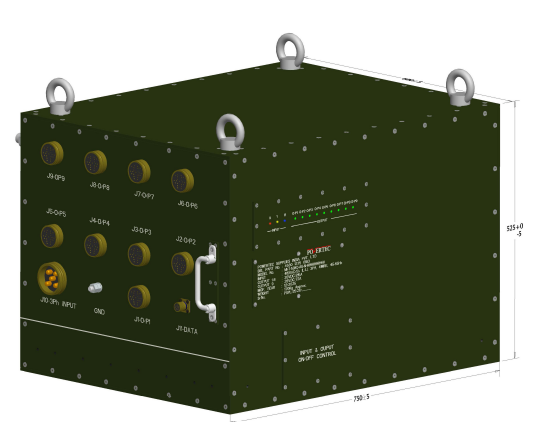
| Handling | Top Eye Bolts |
| Length | <= 750±5mm (excluding Power connectors) |
| Depth | <= 608+0, -2mm (excluding Coolant connectors) |
| Height | <= 525+0, -5mm (excluding Eye bolts) |
| Communication | Ethernet LAN communication for status, fault & functional parameter monitoring of all the incoming, outgoing supply & Rectifier modules including faults. |
| Input Voltage Status | Status of Input Voltage (OK or fault) |
| Rectifier Fault | OVP or desaturation condition |
| Rectifier Status | Status of rectifier (ON/OFF) |
| Temperature | Over temperature trip |
| Output Monitoring | Monitoring of output voltage, current, power |
| Cooling Plate | Monitoring of cooling plate temperature |
| Line Monitoring | Monitoring of line voltage, current |
| Input Power Factor | Monitoring of Input Power Factor |
| Output Voltage Adjustment | Adjustment of Output Voltage range 28V to 30V resolution 0.1V per step, it is real-time V-Adjustment. |
| Output Current Adjustment | Adjustment of Output Current 10A to 220A for O/P 1-8 and 10 to 77A for O/P-9 resolution 1A per step. |
| Rectifier Control | Control of Rectifier ON/OFF (inhibit) |
| Default State | All outputs OFF (inhibit) |
| Individual Output Control | On demand Turn On/Off for each output |
| Remote Monitoring | Remote Monitoring and Alarm over LAN interface |
| Remote Control | Remote Control over LAN interface |
| Sequential Turn ON | Sequential Turn ON of each output with user configurable delays during initial startup (0.5 to 5Sec resolution 0.5Sec 10step + 11th step is manual ON of each output as per user requirement. |
| Sequential Turn OFF | Sequential Turn OFF of each output with user configurable delays based on shut-down command (0.5 to 5Sec resolution 0.5Sec 10step + 11th step is manual OFF of each output as per user requirement. |
| Input Under Voltage Trip | The input under voltage trip works below 330VAC, recycled to restore by GUI application Master On /Off button after fault removal. |
| Trip Threshold | Input under voltage trip at <330VAC Phase to Phase or <165VAC any R, Y, B phase, monitoring on GUI application. |
| Soft Start | Provided |
| Rack Profiles and Covers | All rack profiles, covers shall be in Aluminium 64430 HE 30 Alloy, all aluminium parts should have chromate conversion coating. |
| Steel Parts | All Steel (MS) should have zinc coating |
| External Frames & Panels | Olive Green (BEL Code: PS 613-G-SGL) |
| Fasteners | All fasteners to be of stainless steel, AISI 304 Grade |
| Weight | Weight < 130Kg, cooling liqued weight exclusive. |
| Identification | Vendor Name, Part Number, Serial Number, Manufacturing date, Dimension and Weight data to be indicated as suitable. |
| BEL Markings | BEL Logo, BEL Part Number and Serial Number to be provisioned on the front fascia of the rectifier. |
| Warning Markings | Necessary Warning and Danger symbol to be indicated. |
| Input and Output Markings | All the markings for the input and output connections on Front panel should be engraved, legible and have black back ground colour and finished with clear lacquer. |
| Circuit Diagram | Schematic/Circuit Diagram to be pasted on rectifier module suitably |
| 3D Model | 3D model of the final rectifier to be shared with BEL for system mounting arrangements |
| Mounting Arrangements | Mounting Arrangements for Slides to be provided (Slides will be in BEL Scope) |
| Analysis | Thermal analysis and structural analysis to be submitted to BEL during design review. |
| Acceptance Test Procedure | The Rectifier will be accepted on completion of Functional Tests, Sinusoidal Vibration, High Temperature Operation test, Damp Heat and Low Temperature operation test. Facility for test will be provided by BEL free of cost for one iteration only. |
| 1 | 1 No of 50KW Rectifier 28V |
| 2 | Test Reports from OEM |
| 3 | Certificate of Confirmance |
| 4 | User Manual, Technical Manual, User Handbook, Maintenance Manual, MTBF and MTTR reports |
| Critical BOM | List of critical BOM (datasheets) and MRLS to be provided during the PDR stage along with NSN numbers. |
| Spare Stock | Vendor has to stock necessary spares pertaining to the rectifier for ensuring shortest down time during warranty and failure. |
| Warranty Period | Warranty of 2 years from date of acceptance at BEL. |
| Warranty Extension | Warranty will be extended by the duration of down time/failure. BEL will promptly send a written mail to vendor from the date of failure till completion of rectification by vendor to satisfaction of BEL. |
| MTTR | <=30 mins for individual power module level replacement. |
Input Connector # RGMR02050M40BWR (5Contacts 0 Size Male) J-10 On PSU-Panel
Input Mating Connector # RGMFM06050F40BWR (5Contacts 0 Size female)
| Sr. No | Pin | Contact Size | Reference | Detail |
|---|---|---|---|---|
| 1 | A | 0 | Input Line R Phase | Input Line R Phase |
| 2 | B | 0 | Input Line Y Phase | Input Line Y Phase |
| 3 | C | 0 | Input Line B Phase | Input Line B Phase |
| 4 | N | 0 | Input Neutral / Return | Input Neutral / Return |
| 5 | G | 0 | GND / Chassis Ground | GND / Chassis Ground |
Output-1 to 9 # MGR 02R 28 - 15S B051 C30 101E SQGBM (35 Contact 16 Size Female) J-1 to J-9 On PSU Panel
Mating Connector # MGR 06M 28-15P C30 101 (35 Contact 16 Size Male)
| Sr. No | Pin | Contact Size | Reference / Detail |
|---|---|---|---|
| 1 | A | 16 | 28VDC(+) |
| 2 | B | 16 | 28VDC(+) |
| 3 | C | 16 | 28VDC(+) |
| 4 | D | 16 | 28VDC(+) |
| 5 | E | 16 | 28VDC(+) |
| 6 | F | 16 | 28VDC(+) |
| 7 | G | 16 | 28VDC(+) |
| 8 | H | 16 | 28VDC(+) |
| 9 | J | 16 | 28VDC(+) |
| 10 | K | 16 | 28VDC(+) |
| 11 | L | 16 | 28VDC(+) |
| 12 | M | 16 | 28VDC(+) |
| 13 | N | 16 | 28VDC(+) |
| 14 | P | 16 | 28VDC(+) |
| 15 | R | 16 | 28VDC(+) |
| 16 | S | 16 | 28VDC(+) |
| 17 | T | 16 | 28VDC(+) |
| 18 | U | 16 | 28VDC(-) Reference |
| 19 | V | 16 | 28VDC(-) Reference |
| 20 | W | 16 | 28VDC(-) Reference |
| 21 | X | 16 | 28VDC(-) Reference |
| 22 | Y | 16 | 28VDC(-) Reference |
| 23 | Z | 16 | 28VDC(-) Reference |
| 24 | a | 16 | 28VDC(-) Reference |
| 25 | b | 16 | 28VDC(-) Reference |
| 26 | c | 16 | 28VDC(-) Reference |
| 27 | d | 16 | 28VDC(-) Reference |
| 28 | e | 16 | 28VDC(-) Reference |
| 29 | f | 16 | 28VDC(-) Reference |
| 30 | g | 16 | 28VDC(-) Reference |
| 31 | h | 16 | 28VDC(-) Reference |
| 32 | j | 16 | 28VDC(-) Reference |
| 33 | k | 16 | 28VDC(-) Reference |
| 34 | l | 16 | 28VDC(-) Reference |
| 35 | m | 16 | Blank NA |
Data # D38999/20WB35SN (13contact Female) J-11 On PSU Panel
Data Mating # D38999/26WB35PN (13contact Male)
| Sr. No | Pin | Contact Size | Reference |
|---|---|---|---|
| 1 | 1 | 22D | DA+ (WHITE-ORANGE) |
| 2 | 2 | 22D | DA- (ORANGE) |
| 3 | 3 | 22D | DB+ (WHITE GREEN) |
| 4 | 4 | 22D | DC+ (BLUE) |
| 5 | 5 | 22D | DC- (WHITE-BLUE) |
| 6 | 6 | 22D | DB- (GREEN) |
| 7 | 7 | 22D | DD+ (WHITE-BROWN) |
| 8 | 8 | 22D | DD- (BROWN) |
| 9 | 9 | 22D | NA |
| 10 | 10 | 22D | NA |
| 11 | 11 | 22D | NA |
| 12 | 12 | 22D | NA |
| 13 | 13 | 22D | NA |
| a) | Input Line Voltage current of R, Y, B Phase and power factor Monitoring. |
| b) | Output Voltage, current and power of all 09 Channels. |
| c) | Sequential delay during on and Off by Local Switch or GUI application switch. Delay timing step 0.5Sec to 5Sec 10 step and 11th step Manual control as per user Requirement. |
| d) | Temperature monitoring of all cooling plate and maximum value will be display on application. |
| e) | Status of rectifier ON /OFF of common master and individual 09 outputs. |
| a) | Sequential delay timing can be set as per user requirement 0.5Sec to 5Sec 10 step and 11th step Manual control. |
| b) | Output over Current trip control between 10 to 220Amp (minimum step 1.0Amp) for Output -1 to 8. For 9th output current trip control between 10 to 77Amp (minimum step 1.0Amp). |
| c) | Output voltage adjustment check 28VDC to 30VDC (minimum step 0.1VDC) for Output -1 to 9. |
| a) | Input Over voltage protection at >540VAC Phase to Phase or >270VAC any R, Y, B. |
| b) | Output Over voltage protection >30.3VDC. Recovery after manual set in nominal range, OFF and ON by GUI Application and. |
| c) | Output over current protection settable by GUI application. Recovery after manual set in nominal range by GUI Application. |
| d) | Over temperature protection >80°C recover auto at <75°C |
| e) | Input Under voltage protection at <330VAC Phase to Phase or <165VAC any R, Y, B. |


