

ORing MOSFET: How MOSFET-Based Power Redundancy Works
Discover how ORing MOSFET technology works, its advantages over conventional diode-based ORing, and how it supports efficient redundant power systems in industrial, railway, defence and mission-critical applications.
Explore Powertec Power SolutionsModern industrial, railway, communication, defence and other mission-critical power systems often require more than a single power source. When continuous operation is important, multiple power supplies may be connected to a common load so that the system can continue operating if one power source becomes unavailable.
An ORing MOSFET is a power-management technology used in redundant power architectures to control current flow between multiple power sources while helping reduce the conduction losses associated with conventional diode-based ORing.
MOSFET-based ORing can be used in applications where efficiency, power dissipation, redundancy and reliable power-path management are important.
For applications where power continuity is critical, selecting the right ORing MOSFET solution requires consideration of voltage, current, conduction losses, thermal conditions, protection, control architecture and the complete power-system design.
What Is an ORing MOSFET?
An ORing MOSFET is a MOSFET-based power-path solution used to combine multiple power sources while controlling unwanted reverse current between them.
In a redundant power system, two or more power supplies may provide power to a common load.
Power Supply B → ORing MOSFET → Common Load
The ORing circuitry helps control the direction of current so that a fault or voltage difference in one power source does not unnecessarily feed current back towards another power source.
MOSFET-based ORing can provide a low-resistance power path compared with conventional diode-based arrangements, depending on the MOSFET and control architecture.
When Is ORing MOSFET Technology Used?
- Redundant power supplies are required.
- Low conduction losses are important.
- High current needs to be managed.
- Thermal dissipation needs to be reduced.
- Multiple DC power sources feed one load.
- Power-system availability is important.
- Efficient power-path control is required.
Simplified conceptual ORing MOSFET redundant power architecture. Actual circuit topology and MOSFET orientation depend on the controller and application.
How Does an ORing MOSFET Work?
A MOSFET used for ORing acts as a controlled power-path element.
The basic system monitors the voltage conditions of the connected power sources and controls the MOSFET so that the required power path remains available while unwanted reverse current is limited.
Typical ORing MOSFET Architecture
- Multiple DC power sources.
- MOSFETs positioned in the power paths.
- Voltage or current sensing.
- A control or ideal-diode circuit.
- A common load.
- Protection and thermal-management mechanisms.
When one power source is operating normally, its MOSFET power path can conduct current towards the load.
If the source voltage changes or a fault occurs, the control system can respond by changing the MOSFET state to prevent unwanted current flow.
The exact behaviour depends on the ORing controller, MOSFET characteristics, system voltage, load current and power-supply architecture.
Normal Operation
The controlled MOSFET power path allows the available source to supply the load with relatively low conduction resistance.
Fault Condition
The control architecture responds to source voltage or fault conditions to restrict unwanted reverse-current flow.
Why Is MOSFET Used for ORing?
A conventional diode has a forward voltage drop when current flows through it.
At high current, this voltage drop can result in significant power dissipation.
A MOSFET-based ORing design can use the MOSFET's low on-state resistance to create a lower-resistance current path under suitable operating conditions.
Where:
- I: Current flowing through the MOSFET.
- RDS(on): MOSFET drain-to-source on-state resistance.
Example Power Loss Calculation
If a MOSFET has a hypothetical RDS(on) of 10 milliohms and carries 20A:
Power Loss = 4W
The actual power loss depends on the MOSFET, temperature, current, gate-drive conditions and complete circuit design.
This is why MOSFET selection and thermal analysis are important when designing an ORing power system.
ORing MOSFET vs ORing Diode
Both ORing diodes and ORing MOSFETs can be used to provide power-path isolation and redundancy. However, their electrical characteristics are different.
| Feature | ORing Diode | ORing MOSFET |
|---|---|---|
| Main Function | Power-path isolation | Power-path isolation |
| Main Device | Diode | MOSFET |
| Conduction | Forward voltage drop | RDS(on)-dependent loss |
| Control | Generally simple | Usually requires control circuitry |
| Power Loss | Can increase with current | Can be lower in suitable designs |
| Thermal Requirements | Increase with current | Depend on current and RDS(on) |
| Circuit Complexity | Generally lower | Generally higher |
| Applications | Redundant power systems | High-efficiency redundant systems |
The appropriate technology depends on voltage, current, efficiency target, thermal environment and system architecture.
What Is RDS(on)?
RDS(on) is the drain-to-source resistance of a MOSFET when it is turned on.
It is one of the important specifications when evaluating MOSFET-based power paths.
Lower RDS(on) generally means lower conduction losses at a given current.
This means conduction losses can increase significantly as current increases.
For example, doubling current increases the I² component four times if resistance remains constant.
Important MOSFET Selection Parameters
- MOSFET RDS(on).
- Current.
- Junction temperature.
- PCB layout.
- Thermal resistance.
- Cooling.
- Gate-drive conditions.
Why Thermal Management Matters in ORing MOSFET Systems
Even though MOSFET-based ORing can provide a low-resistance power path, the device still generates heat during operation.
Heat generation depends on:
- Load current.
- RDS(on).
- Ambient temperature.
- MOSFET junction temperature.
- Switching behaviour.
- PCB design.
- Cooling method.
If current is high, even a small resistance can produce meaningful heat.
Thermal Design Considerations
PCB Thermal Design
Large PCB copper areas and thermal vias can help distribute heat away from the MOSFET.
Cooling Methods
Heat sinks, forced airflow and conduction cooling can be considered depending on the design.
Enclosure Design
Appropriate enclosure and mounting arrangements help maintain operating temperatures.
Temperature Monitoring
Temperature monitoring can support protection and system reliability.
The actual thermal design should always use the manufacturer's MOSFET and controller specifications.
ORing MOSFET for Redundant Power Supplies
One of the most important applications of ORing MOSFET technology is redundant power supply design.
A redundant power architecture can use two or more power supplies connected to a common load.
Power Supply B → ORing MOSFET B → Load
If Power Supply A fails, the second power path can continue supplying the load if it has sufficient capacity.
Typical Applications
- Industrial automation.
- Railway equipment.
- Telecom systems.
- Defence electronics.
- Control systems.
- Mission-critical infrastructure.
The actual redundancy configuration depends on the system's required availability, load profile and power-supply specifications.
ORing MOSFET and Power Supply Redundancy
Power redundancy is used when a system needs to continue operating even if one power source becomes unavailable.
An ORing MOSFET can form part of this architecture by providing controlled power paths between individual sources and the load.
This architecture can help separate the power sources while allowing the load to receive power from an available source.
However, ORing alone does not guarantee redundancy.
Complete Redundant System Considerations
- Independent power sources.
- Converter reliability.
- Current capacity.
- Load sharing.
- Fault detection.
- Protection.
- Thermal management.
- Wiring.
- Monitoring.
- Maintenance requirements.
ORing MOSFET for Industrial Applications
Industrial automation systems can use multiple power supplies to support PLCs, controllers, sensors, communication equipment and control panels.
A power failure in one supply can interrupt an entire process if no suitable backup architecture is available.
ORing MOSFET technology can be incorporated into industrial redundant power systems where efficiency and power-path management are important.
Industrial Applications
- PLC systems.
- Industrial control panels.
- Factory automation.
- Robotics.
- Instrumentation.
- Communication equipment.
- Remote monitoring.
- Industrial computers.
Powertec Industrial Power Solutions
Powertec's industrial portfolio includes DC/DC converters, AC/DC power supplies and specialised power solutions for industrial applications.
Explore Industry SolutionsORing MOSFET for Railway Power Systems
Railway systems can require reliable power conversion and redundancy because electrical equipment may need to operate continuously under demanding conditions.
Railway power systems can experience:
- Voltage transients.
- Electrical disturbances.
- Shock.
- Vibration.
- Temperature variations.
- EMC requirements.
Power redundancy can therefore be an important part of railway system architecture.

Railway Power Technology
Powertec specifically showcases ORing MOSFET power systems among its railway-related power technologies. Its railway portfolio also includes redundant power systems and specialised DC/DC converters.
Explore Railway SolutionsFor railway applications, the complete power system should be evaluated against the relevant electrical, environmental and railway standards.
ORing MOSFET for Defence Applications
Defence systems can require reliable power architectures for electronic equipment operating under demanding environmental and electrical conditions.
ORing MOSFET technology may be considered where:
- Multiple power sources are required.
- High efficiency is important.
- Power redundancy is required.
- Thermal losses need to be controlled.
- Continuous power availability is important.
Powertec's portfolio includes rugged power-conversion products for defence and military applications, including specialised AC/DC and DC/DC systems.
Explore Defence SolutionsThe exact ORing architecture should be selected according to the electrical and environmental requirements of the particular defence system.
ORing MOSFET for Communication Systems
Communication and telecom equipment often requires stable DC power because an interruption can affect network availability.
A redundant DC power system may use:
This allows multiple power paths to support the same system.
Important Considerations
- Input voltage.
- Output voltage.
- Maximum current.
- Power capacity.
- Thermal performance.
- Reverse-current protection.
- Fault response.
- Monitoring.
- System redundancy.
The final ORing solution should be evaluated according to the complete power architecture.
ORing MOSFET for 24V DC Systems
24V DC systems are widely used in industrial control and automation applications.
An ORing MOSFET arrangement can allow multiple 24V DC power sources to support a common load.
The MOSFET and control circuit should be selected according to:
- Maximum input voltage.
- Continuous current.
- Peak current.
- RDS(on).
- Thermal conditions.
- Fault response.
- Required redundancy.
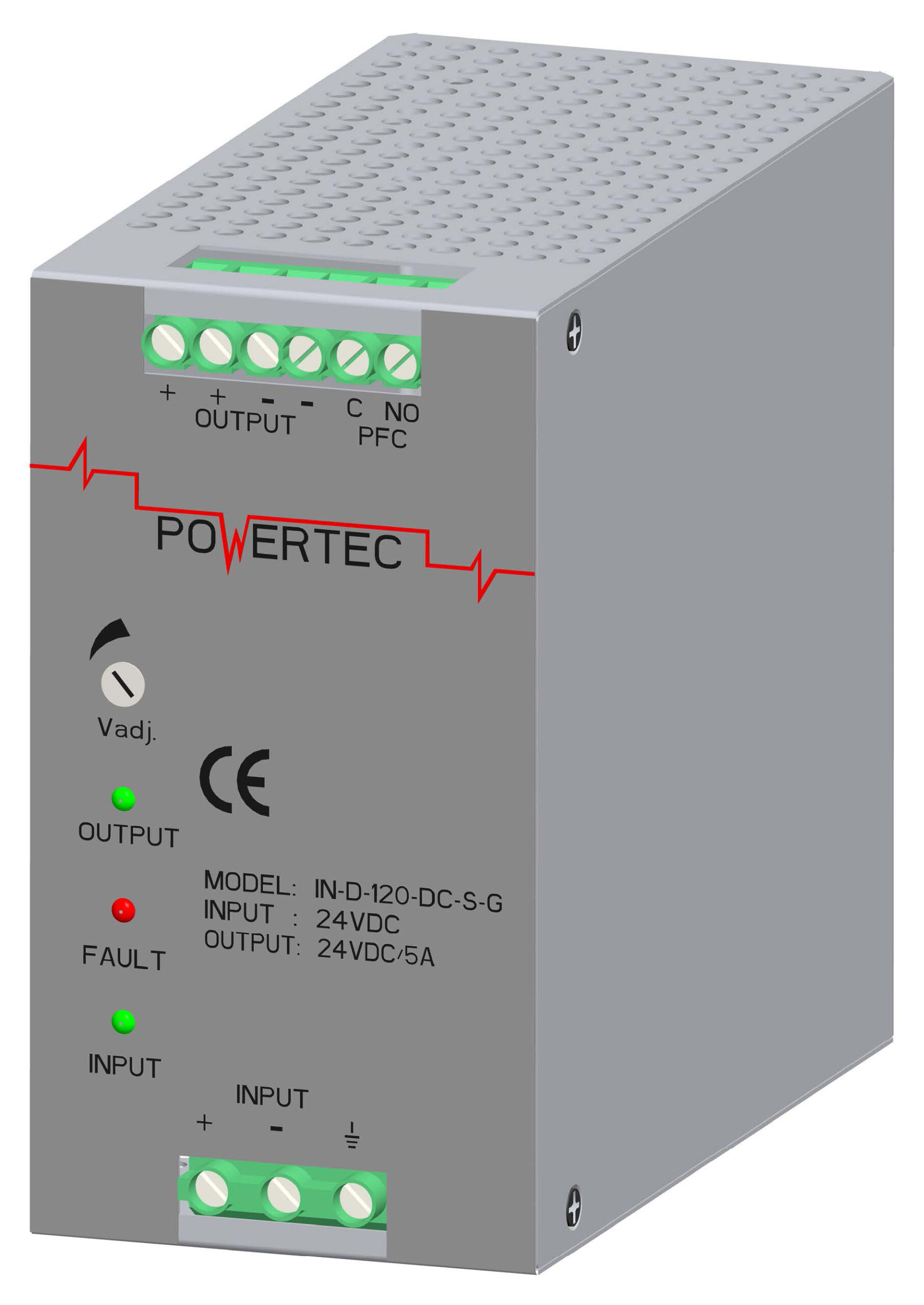
Powertec's DC/DC converter portfolio includes 24V DC products with integrated ORing functionality. The IN-D-120-DC-S-G, for example, is specified as a 24VDC input / 24VDC output converter with 120W output and an integrated ORing diode for redundancy and power sharing.
View 24V DC/DC ConverterThis is a diode-ORing converter example, not a claim that the product contains an ORing MOSFET.
ORing MOSFET for 48V DC Systems
48V DC systems are commonly used in various industrial and communication power architectures.
A 48V DC redundant system can use multiple power sources with an ORing power path.
48V DC Supply B → ORing → Load
Where a DC/DC converter is required, a suitable converter can provide the required downstream voltage.
IN-D-120-DD-S-G
48VDC Input / 24VDC Output
This Powertec 120W DC/DC converter includes integrated diode ORing for redundancy and parallel operation.
View ProductThe product is a relevant DC/DC converter example, but its integrated ORing diode should not be confused with a MOSFET-based ORing implementation.
ORing MOSFET and High-Current Power Systems
High-current applications require careful consideration of conduction losses.
Because conduction loss is related to:
Even a small increase in current can significantly increase power dissipation.
High-Current Design Considerations
- MOSFET selection.
- Parallel MOSFET configuration.
- RDS(on).
- PCB copper.
- Thermal resistance.
- Gate-drive performance.
- Current sharing.
- Protection.
- Cooling.
A high-current power system should always be evaluated using actual operating conditions rather than relying only on nominal component ratings.
ORing MOSFET Protection Features
Depending on the design, an ORing MOSFET system can incorporate several protection functions.
Electrical Protection
- Reverse-current protection.
- Over-voltage protection.
- Over-current protection.
- Short-circuit protection.
System Protection
- Over-temperature protection.
- Surge protection.
- Transient protection.
- Fault monitoring.
- Under-voltage protection.
The exact functions depend on the MOSFET, controller and complete ORing circuit.
Engineers should verify the manufacturer's datasheet before selecting a specific device.
How to Choose the Right ORing MOSFET
Before selecting an ORing MOSFET solution, engineers should evaluate the following specifications.
1. Maximum Voltage
Check the maximum continuous and transient voltage that the MOSFET must withstand.
2. Current Rating
Determine maximum continuous and peak current. Consider thermal conditions rather than relying only on the headline current rating.
3. RDS(on)
Check the MOSFET's on-state resistance under actual gate-drive and temperature conditions.
4. Power Dissipation
Estimate conduction losses using PLOSS = I² × RDS(on).
5. Thermal Performance
Consider junction temperature, ambient temperature, PCB thermal design, heat sinks, airflow and enclosure.
6. Reverse-Current Blocking
Verify that the ORing controller and MOSFET architecture provide the required reverse-current blocking behaviour.
7. Switching Behaviour
Evaluate response time and switching characteristics for the intended application.
8. Gate-Drive Requirements
Check gate voltage, gate charge, controller compatibility and drive capability.
9. Redundancy Architecture
Determine whether the system requires:
- 1+1 redundancy.
- N+1 redundancy.
- Parallel power supplies.
- Load sharing.
- Backup power.
10. Environmental Conditions
- Operating temperature.
- Humidity.
- Vibration.
- Altitude.
- Electrical transients.
- EMC requirements.
ORing MOSFET vs Conventional Diode: Which Should You Use?
There is no single solution that is appropriate for every application.
A conventional diode-based ORing solution may be attractive where simplicity and straightforward implementation are important.
A MOSFET-based ORing architecture may be considered where lower conduction losses and higher efficiency are important.
Factors to Consider
- Voltage.
- Current.
- Efficiency.
- Thermal limits.
- Response requirements.
- Circuit complexity.
- Cost.
- Reliability requirements.
- Application environment.
For high-current or efficiency-sensitive systems, the reduction in conduction loss can become an important design consideration.
For simpler systems, a conventional diode solution may still be appropriate.
Why Choose Powertec for ORing and Power Redundancy Solutions?
Powertec Supplies India Pvt. Ltd. provides power conversion solutions for industrial, railway, defence, medical and other critical applications.
Its portfolio includes:
- DC/DC converters.
- AC/DC converters.
- ORing solutions.
- Automatic transfer switches.
- Specialised power systems.
- Custom power solutions.
Powertec's website specifically highlights ORing MOSFET power systems as part of its power technology offering, while its product portfolio also includes DC/DC converters with integrated ORing diode functionality.
Powertec Power Conversion Solutions
Powertec provides specialised power solutions for industrial, railway, defence and other demanding applications.
Its portfolio includes products designed around different voltage, current, power and redundancy requirements.
Explore Powertec Contact Sales TeamIts railway portfolio includes power systems designed for railway applications, including redundant configurations and specialised DC/DC conversion solutions.
For engineers developing a redundant power system, Powertec can provide application-specific power-conversion options depending on the required voltage, current, power, redundancy and environmental conditions.
Final Thoughts
Choosing the right ORing MOSFET solution requires an engineering evaluation of voltage, current, RDS(on), conduction losses, thermal performance, reverse-current blocking, control requirements, protection and system architecture.
MOSFET-based ORing can provide an efficient power-path solution for redundant power systems when properly designed and matched to the application.
From industrial automation and railway systems to communication, defence and other mission-critical applications, ORing MOSFET technology can form an important part of a reliable redundant power architecture.
Powertec Supplies provides specialised power-conversion solutions and showcases ORing MOSFET technology for applications including railway power systems.
If you are designing a redundant power system or evaluating an ORing MOSFET solution, consider the complete voltage, current, thermal, protection and redundancy requirements before selecting the final design.
Frequently Asked Questions About ORing MOSFET
1. What is an ORing MOSFET?
An ORing MOSFET is a MOSFET-based power-path solution used to combine multiple power sources while controlling unwanted reverse current between them.
2. How does an ORing MOSFET work?
An ORing MOSFET uses a controlled semiconductor power path to allow current to flow towards a common load while helping restrict unwanted reverse-current flow.
3. What is the difference between an ORing MOSFET and an ORing diode?
An ORing diode uses its forward voltage characteristics to control current direction. An ORing MOSFET uses a controlled low-resistance power path that can reduce conduction losses under suitable operating conditions.
4. What does RDS(on) mean in an ORing MOSFET?
RDS(on) is the drain-to-source resistance of a MOSFET when it is switched on. It determines an important part of the device's conduction losses.
5. Why is MOSFET ORing suitable for high-current applications?
MOSFET-based ORing can offer lower conduction losses compared with conventional diode-based ORing in suitable designs, making it useful for evaluating high-current power architectures.
6. Can ORing MOSFETs be used in redundant power supplies?
Yes. ORing MOSFETs can form part of redundant power supply architectures where multiple sources support a common load.
7. Why is thermal management important in ORing MOSFET systems?
MOSFETs generate heat due to their on-state resistance and current. Appropriate PCB design, cooling and thermal monitoring help maintain safe operating temperatures.
8. Where are ORing MOSFET systems used?
They can be used in industrial automation, railway equipment, defence electronics, communication systems and other mission-critical power applications.
9. What should engineers consider when selecting an ORing MOSFET?
Important factors include maximum voltage, current, RDS(on), power dissipation, thermal conditions, gate-drive requirements, reverse-current blocking, protection and redundancy architecture.
10. Does Powertec offer ORing MOSFET technology?
Powertec showcases ORing MOSFET power systems among its power technologies, including its railway-related portfolio. Contact Powertec for application-specific requirements.
Looking for an ORing MOSFET or Redundant Power Solution?
Discuss your voltage, current, power redundancy and application requirements with Powertec Supplies. Find the right power solution for industrial, railway, defence and mission-critical applications.
Explore Railway Solutions Contact PowertecPowertec Supplies India Pvt. Ltd.