

ORing Diode: Working, Benefits, Applications and How to Choose the Right One
Understand how ORing diodes work, how they support redundant power supplies, and what engineers should consider when selecting an ORing solution for industrial and mission-critical applications.
Explore ORing Diode SolutionsA reliable ORing diode is an important component in power systems where redundancy, power sharing and continuity of operation are required. Industrial automation systems, railway equipment, communication infrastructure and defence electronics may use ORing technology to connect multiple power sources to a common load.
An ORing diode helps prevent unwanted reverse current between connected power sources while allowing an appropriate power source to supply the load. This is especially useful in redundant power architectures where a backup power supply needs to support the load if the primary source becomes unavailable.
Selecting the right ORing diode requires more than matching voltage and current ratings. Forward voltage drop, thermal performance, reverse-current blocking, protection features and the complete system architecture must also be considered.
What Is an ORing Diode?
An ORing diode is a power semiconductor component used to combine multiple power sources while helping prevent current from flowing backward from one source into another.
The term ORing refers to electrically combining multiple power paths so that a load can receive power from an available source.
Simplified illustration of a two-source diode ORing architecture. Actual circuit design depends on polarity, grounding and protection requirements.
A simplified redundant power system can be represented as:
Power Supply B → ORing Path B → Common Load
If Power Supply A becomes unavailable, Power Supply B can continue supplying the load, provided the complete system is correctly designed and the remaining source has sufficient capacity.
When Is ORing Used?
- Two or more power sources supply one load.
- Power redundancy is required.
- Reverse current needs to be controlled.
- Multiple DC power supplies operate in parallel.
- System availability is important.
- Power supplies need electrical isolation from each other.
How Does an ORing Diode Work?
A diode allows current to flow primarily in one direction while restricting current in the opposite direction.
In an ORing configuration, a diode is placed between each power source and the common load. This arrangement allows the sources to feed the load without providing an unrestricted reverse-current path between their outputs.
Normal Operation
When both sources are available, their ORing paths operate according to their voltage levels, diode characteristics and system design.
Source Failure
If one source fails or its output falls sufficiently, the other available source can support the load if it has enough capacity.
The exact behaviour depends on:
- Input and output voltage.
- Diode forward voltage.
- Load current.
- Power supply characteristics.
- Wiring resistance.
- Thermal conditions.
- Redundancy architecture.
For this reason, ORing should be designed as part of the complete power system rather than treated as an isolated component.
Why Is ORing Used in Power Supplies?
ORing is commonly used to improve the availability of a power system.
Consider a system with two independent DC power supplies connected to a common load. Without an appropriate isolation method, a voltage difference or fault between the supplies could allow unwanted current to flow from one power source towards another.
An ORing arrangement helps control this interaction.
Power-Source Isolation
Helps prevent unwanted reverse-current flow between connected power sources.
Redundant Power
Supports backup power architectures in which another source can supply the load.
Fault Isolation
Helps limit the interaction between power paths when one source experiences a fault.
System Availability
Can reduce the risk of a single power-source failure interrupting the entire load.
Powertec's DC/DC converter range includes selected models with integrated ORing diodes for redundancy and power sharing.
ORing Diode for Redundant Power Supplies
One of the most common applications of an ORing diode is a redundant power supply system.
A redundant power system can use two or more power supplies to support one load.
Power Supply A: 24V DC
Power Supply B: 24V DC
Isolation: ORing paths
Common Load: 24V DC
If both supplies are available, the system operates according to its intended redundancy or parallel-power architecture. If one supply fails, the other can continue supporting the load if it has sufficient capacity.
Typical Applications
- Industrial automation.
- Railway equipment.
- Communication systems.
- Control systems.
- Defence electronics.
- Mission-critical infrastructure.
The actual redundancy configuration should always follow the power supply specifications and application requirements.
ORing Diode and Parallel Power Supplies
ORing can also be used when multiple power supplies are connected in a system designed for parallel operation.
However, simply connecting two power supplies together does not automatically create a reliable redundant power system.
Engineers should consider:
- Output voltage matching.
- Current sharing.
- ORing voltage drop.
- Thermal dissipation.
- Protection coordination.
- Power supply regulation.
- Fault behaviour.
- Load requirements.
Powertec's IN-D-120-DC-S-G is an example of a DC/DC converter with an integrated ORing diode for redundancy and power sharing. It provides 24VDC input and 24VDC output, with 120W output power and 5A output current.
What Is Forward Voltage Drop?
One of the important characteristics of a conventional ORing diode is its forward voltage drop.
When current flows through a diode, a voltage difference exists across the device. The resulting power loss can be approximated using:
Example Calculation
Suppose an ORing diode has a hypothetical forward voltage of 0.5V and the current is 10A.
This 5W becomes heat that must be managed by the system.
The actual forward voltage depends on diode technology, current, temperature and the specific component. Always use manufacturer-specified electrical characteristics when calculating losses.
Why ORing Diode Thermal Management Matters
An ORing diode can dissipate heat during normal operation. As current increases, even a relatively small voltage drop can result in significant power dissipation.
Thermal design may involve:
- Heat sinks.
- PCB copper area.
- Airflow.
- Conduction cooling.
- Appropriate enclosure design.
- Temperature monitoring.
The thermal requirements depend on the diode, current, ambient temperature and mounting arrangement. For integrated ORing solutions, the converter or ORing module's own thermal specifications should be considered.
ORing Diode Protection Features
Depending on the product architecture, an ORing solution may incorporate or work alongside several protection functions.
Electrical Protection
- Reverse-current blocking.
- Reverse-polarity protection.
- Input transient protection.
- Surge protection.
System Protection
- Over-temperature protection.
- Over-current protection.
- Short-circuit protection.
- Fault monitoring.
For example, Powertec's IN-D-120-DC-S-G provides input transient and reverse-polarity protection, together with over-voltage, short-circuit, over-current and over-temperature protection. Its specifications also list an integrated ORing diode for redundancy and power sharing.
ORing Diode for Industrial Applications
Industrial automation systems can require continuous power for controllers, sensors, communication equipment, PLCs, control panels and instrumentation.
A failure in a single power supply can interrupt an entire system if there is no backup power path.
An ORing architecture can be incorporated into a redundant industrial power system to allow multiple power sources to support the load.
Typical Industrial Applications
- 24V DC and 48V DC systems.
- DIN-rail power installations.
- Industrial control cabinets.
- PLC systems.
- Industrial automation.
- Communication equipment.
- Remote monitoring systems.
Powertec's industrial DC/DC converter range includes DIN-rail and back-plane mounting options on selected models, with different input and output configurations.
ORing Diode for Railway Power Systems
Railway applications can require reliable power systems because equipment may need to operate continuously under demanding electrical and environmental conditions.
Power conversion equipment used in railway systems can be exposed to:
- Electrical transients.
- Voltage variations.
- Shock and vibration.
- Temperature variations.
- Electromagnetic compatibility requirements.
Redundant power architectures can therefore be an important part of railway system design.
Powertec ORing Solutions
Powertec's railway portfolio includes specialised redundant DC/DC power systems and ORing MOSFET power technology.
Its catalogue includes a 110VDC-input railway DC/DC converter with a 5VDC/30A redundant output configuration, together with input transient and surge protection.
Explore Railway SolutionsORing and redundancy should always be evaluated according to the specific railway power architecture and applicable standards.
ORing Diode for Mission-Critical Power Systems
Mission-critical systems may require multiple layers of protection and redundancy.
Applications can include:
- Railway systems.
- Defence systems.
- Industrial control.
- Telecommunications.
- Medical equipment.
- Critical infrastructure.
In these applications, an ORing solution can be part of a larger architecture that includes:
The objective is to reduce the possibility that a single power-source failure interrupts the complete load. The appropriate architecture depends on the system's availability requirements and engineering specifications.
ORing Diode vs ORing MOSFET
ORing can be implemented using different semiconductor technologies.
A conventional ORing diode is relatively simple and robust, but its forward voltage drop can create power loss. MOSFET-based ORing or ideal-diode architectures can reduce conduction losses under appropriate operating conditions.
| Feature | ORing Diode | ORing MOSFET |
|---|---|---|
| Basic Function | Reverse-current isolation | Reverse-current isolation |
| Semiconductor | Diode | MOSFET |
| Forward Loss | Depends on diode forward voltage | Depends largely on RDS(on) and control |
| Thermal Loss | Can increase with current | Can be lower in suitable designs |
| Circuit Complexity | Generally simpler | Generally more complex |
| Control Electronics | Usually not required | Often required |
| Applications | Redundant power systems | Advanced redundant power systems |
Powertec also highlights ORing MOSFET power systems among the technologies showcased for railway applications.
Explore ORing MOSFET solutions.
The correct technology depends on voltage, current, efficiency, thermal requirements, response requirements and the complete system architecture.
ORing Diode for 24V DC Systems
24V DC is widely used in industrial control and automation systems. An ORing arrangement can allow two 24V DC power sources to support a common load while helping prevent reverse current between the sources.
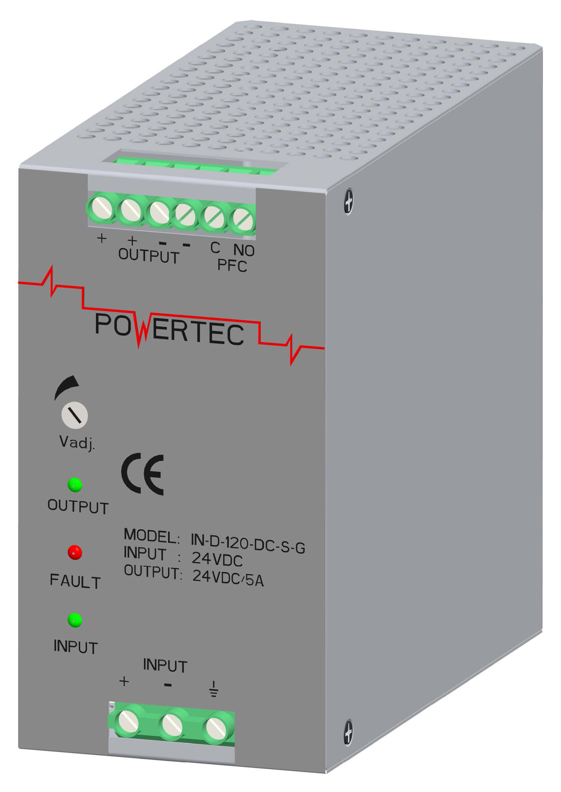
IN-D-120-DC-S-G
120W DC/DC Converter with Integrated ORing Diode
This Powertec converter provides a 24VDC input and 24VDC output and includes an inbuilt ORing diode for redundancy and power sharing.
View ProductTechnical Specifications
| Specification | Details |
|---|---|
| Nominal Input | 24VDC |
| Input Range | 18–36VDC |
| Output Voltage | 24VDC |
| Output Current | 5A |
| Output Power | 120W |
| Cooling | Natural convection |
| Mounting | Back-plane / DIN-rail |
| ORing | Inbuilt ORing diode |
| Protection | Over-current, short-circuit, over-temperature and reverse polarity |
| Efficiency | >87% from 10% to 100% load, excluding diode losses |
ORing Diode for 48V DC Systems
48V DC power systems are also used in industrial, communication and other specialised applications.

IN-D-120-DD-S-G
48VDC Input / 24VDC Output
This 120W DC/DC converter includes an inbuilt ORing diode for redundancy and parallel operation.
View ProductTechnical Specifications
| Specification | Details |
|---|---|
| Nominal Input | 48VDC |
| Input Range | 36–76VDC |
| Output Voltage | 24VDC |
| Output Current | 5A |
| Output Power | 120W |
| Cooling | Natural convection |
| Mounting | Back-plane / DIN-rail |
| ORing | Inbuilt ORing diode |
| Protection | Over-voltage, short-circuit, over-current and over-temperature |
This type of converter can be considered where a 48V DC source needs to provide a regulated 24V DC output within the specified operating conditions.
How to Choose the Right ORing Diode
Before selecting an ORing diode or ORing module, engineers should evaluate the following specifications.
1. Maximum Voltage
Check the maximum continuous and transient voltage the device must withstand.
2. Current Rating
Determine the maximum continuous load current and consider peak operating current.
3. Forward Voltage
A lower forward voltage can reduce conduction losses in a conventional diode ORing architecture.
4. Power Dissipation
Calculate heat generation using the actual electrical characteristics of the device.
5. Thermal Conditions
Evaluate ambient temperature, cooling, enclosure, airflow, mounting and heat sinking.
6. Reverse Current
Ensure the ORing device provides the required reverse-current blocking behaviour.
7. Protection
Evaluate reverse-polarity, over-temperature, over-current, surge and transient protection requirements.
8. Redundancy Architecture
Determine whether the system requires 1+1 redundancy, N+1 redundancy, parallel operation, load sharing or backup power.
9. Mounting Requirements
- DIN-rail mounting.
- Cabinet mounting.
- PCB mounting.
- Back-plane mounting.
10. Environmental Conditions
- Operating temperature.
- Humidity.
- Vibration and shock.
- Altitude.
- Electrical transients.
- EMC requirements.
Why Choose Powertec for ORing and Redundant Power Solutions?
Powertec Supplies India Pvt. Ltd. develops and supplies power conversion solutions for industrial, railway, defence, medical and other critical applications.
Its portfolio includes:
- DC/DC converters.
- AC/DC converters.
- ORing diode solutions.
- ORing MOSFET power systems.
- Automatic Transfer Switches.
- Specialised power systems.
Powertec ORing Diode Range
Powertec offers ORing diode products in different power configurations, including selected models with DIN-rail mounting, low forward drop and protection features.
Explore ORing Products Custom SolutionsIts DC/DC converter range also includes products with integrated ORing functionality.
For example, the IN-D-120-DC-S-G provides 24VDC input and 24VDC output at 120W and includes an inbuilt ORing diode for redundancy and power sharing.
The 48VDC-to-24VDC IN-D-120-DD-S-G similarly includes an inbuilt ORing diode for redundancy and parallel operation.
Powertec also showcases ORing MOSFET power systems as part of its railway power technology portfolio.
Product selection should be based on the electrical, mechanical and environmental requirements of the intended application.
Final Thoughts
Choosing the right ORing diode requires an engineering evaluation of voltage, current, forward voltage, power dissipation, thermal conditions, protection, redundancy requirements and system architecture.
ORing technology can be an important part of redundant power systems where multiple power sources need to support a common load while limiting unwanted reverse current.
From industrial automation and railway systems to communication, defence and other mission-critical applications, ORing should be selected according to the actual electrical and environmental requirements of the system.
Powertec Supplies provides power conversion solutions that incorporate ORing functionality in selected DC/DC converter products and offers specialised power solutions for industrial and critical applications.
If you are designing a redundant power system or need an ORing solution for your application, evaluate the required voltage, current, redundancy architecture, thermal conditions and protection requirements before selecting the final product.
Frequently Asked Questions About ORing Diodes
1. What is an ORing diode used for?
An ORing diode combines multiple power sources into a common load while helping prevent unwanted reverse-current flow between the connected sources. It is commonly used in redundant DC power systems.
2. How does an ORing diode work?
An ORing diode allows current to flow from an available power source towards the load while restricting reverse current towards the other connected sources.
3. What is the difference between an ORing diode and an ORing MOSFET?
A conventional diode uses its forward voltage characteristics to control current direction. An ORing MOSFET uses semiconductor switching and control circuitry to achieve reverse-current blocking, potentially with lower conduction losses.
4. Can ORing diodes be used with 24V DC power supplies?
Yes. ORing arrangements are commonly used in 24V DC industrial power systems where multiple supplies need to support a common load.
5. Can two power supplies be connected in parallel using ORing?
Yes, when the power supplies and ORing architecture are designed for the intended parallel operation. Voltage matching, current sharing, thermal performance and protection must be evaluated.
6. What causes power loss in an ORing diode?
Power loss primarily occurs due to the diode's forward voltage drop when current flows through it. It can be estimated using forward voltage multiplied by current.
7. Why is thermal management important in ORing systems?
Forward voltage drop creates heat during normal operation. Appropriate cooling and thermal design help maintain safe operating temperatures and reliable performance.
8. Does Powertec provide ORing diode solutions?
Yes. Powertec Supplies offers ORing diode products, specialised ORing solutions and DC/DC converters with integrated ORing functionality in selected models.
9. What should engineers check before selecting an ORing diode?
Engineers should evaluate maximum voltage, continuous current, forward voltage, power dissipation, thermal conditions, reverse-current blocking, protection features, mounting and environmental requirements.
Looking for an ORing Diode or Redundant Power Solution?
Discuss your voltage, current, redundancy architecture and application requirements with Powertec Supplies. Find the right power solution for your industrial, railway or mission-critical application.
Explore ORing Diodes Contact PowertecPowertec Supplies India Pvt. Ltd.