

Home /PTC-O-AFDC-O-C-DGGGGGGJ-A
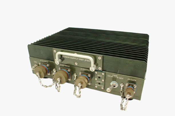
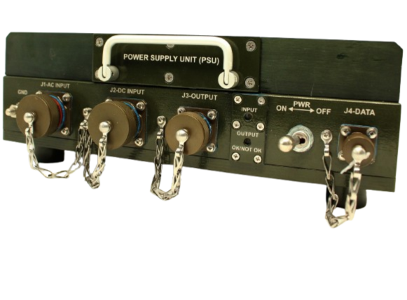
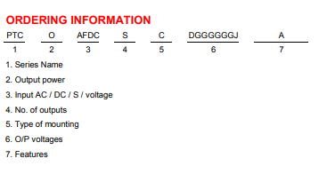
| Input | Dual Input |
| Input-AC | 230VAC±10%, 47-53Hz, Single phase |
| Input-DC | 24VDC (+20 to +36VDC) |
| Current | 4.0A Max. with AC input & 40A Max. with DC input. |
| Input priority | AC input in priority, auto switch to DC input when AC input fail or unavailable. |
| Isolation |
I/P to O/P : 500 VDC 10Mῼ I/P to Chassis : 500 VDC 10Mῼ O/P to Chassis : 500VDC, 10Mῼ |
| Protection | AC Input over voltage >258VAC and under voltage <180VAC and over current with fuse, lightening, surge & DC input reverse polarity, DC input under voltage <18VDC Over voltage>36VDC. |
| Input Power factor | ˃0.9 for AC input. |
| Earth leakage current | ˂1mAmp. |
| Optional O/Ps port | Any one O/P Shall be use from 24/13A or 48VDC/5.5A at a time |
| Operating Temperature | -30°C to +55°C. |
| Storage Temperature | -40°C to +70°C. |
| Relative Humidity | 20-95% RH (Non-condensing). |
| Cooling | Natural / external forced air convection cooling. |
| Altitude | 5500Mtr. |
| Weather proofing | IP-65 / Rain test |
| Input AC J-1 & DC J-2 | D3899920WF11PN (11 Pin male) with dust cap. |
| Output J-3 | D3899920WD35SN (37 Pin female) with dust cap. |
| Data J-4 | SNTs144K/20-W-A-9PN with dust cap. |
| Input harness W-1 | (2Mtr cable length) with one end radial mating connector D3899926WF11SN of input PWR. Other Y side one part should have single phase15A plug top other part should have Y lug / eyelet for DC input. It is common for AC and DC input. |
| Output harness W-2 | (1Mtr cable) with one end mating connector D3899926WD35PN output PWR. Other Y side one part should have mating connector J1- D38999/26WD35SN and other part should have mating connector J1-D38999/26WC98SN. |
| Output-1 | Output-2 | Output-3 | Output-4 | Output-5 | Output-6 | Output-7 | Output-8 | |
|---|---|---|---|---|---|---|---|---|
| Voltage | 12VDC | 24VDC | 24VDC | 24VDC | 24VDC | 24VDC | 24VDC | 48VDC |
| Current | 2.0A | 1.0A | 2.0A | 1.0A | 2.0A | 8.0A | 13A | 5.5A |
| Power | 24W | 24W | 48W | 24W | 48W | 192W | 312W | 264W |
| Output over voltage protection | >13.0 to 13.5V >26 to 27V >26 to 27V >51 to 53V | |||||||
| Output over current protection | >3.5 to 3.7A >16.10 to 16.5A >16.10 to 16.5A >6.5 to 7.0A | |||||||
| Output voltage tolerance | ±5.0% of Vnom. On PSU connector pin (output harness line drop extra). | |||||||
| Ripple (mVp-p) | <1.0% of Vnom outputs with 1µf ceramic at RF probe. Measurement on PSU connector pin. | |||||||
| Common negative |
Output-1 negative reference C-1 and Output -2, 3, 4, 5, 6, 7 Port-out with common negative C-2 Internal Output-8 Port-out with common negative C-3. |
|||||||
| Line regulation | 1.0% of Vnom. On PSU connector pin (output harness line drop extra). | |||||||
| Load regulation | 1.0% of Vnom on PSU connector pin (output harness line drop extra). | |||||||
| LED indicator | Input indicator red and all outputs common health Indicator green if all output are ok. If all or any one output not ok than indicator red. | |||||||
| Health status | Health status of all outputs port provided on data connector user shall be confirm-Protocol & status type. | |||||||
| On/Off control | On/off control switch provided on PSU face plate. | |||||||
| Protection | Over voltage over current short ckt protected. In case of O/V & O/C respective output voltage should be off and recovery auto Hicc-up mode when fault condition remove. check pulse cycle is 2Sec.Output 2 to 6 are with common converter so O/V and O/C protection will be common. | |||||||
| Over-Temperature Protection | Protected (trip between ≥ 90-95⁰C & recovery at 80 to 85⁰C) monitoring on Heat sink. | |||||||
| Salt Corrosion | PCB conformal coated. | |||||||
| Efficiency | >80±1% At full load with nominal input. | |||||||
| Environment Std | JS55555. |
| High temperature | Operating 55±3°C duration 16Hrs. Storage 70±3°C duration 16Hrs. |
| Low temperature | Operating -30±3°C duration 16Hrs. Storage -40±3°C duration 16Hrs. |
| Damp Heat | Temp +40±2°C RH95% duration 16Hrs. |
| Altitude | Operating temp at -30±3°C. Altitude 5500Mtr(60kpa). |
| Thermal Shock | Temp at 55±3°C for duration 3Hrs RH <30%. |
| EMI / EMC | MIL Std 461E |
| CE102 | Conduction emissions power leads 10KHz to10MHz 9db limit relaxation for AC input. |
| CS101 | Conducted susceptibility power lead 30Hz to 150KHz. |
| CS114 | Conducted susceptibility bulk cable injection 10Khz to 200MHz. |
| CS115 | Conducted susceptibility bulk cable injection impulse excitation. |
| CS116 | Conducted susceptibility damped sinusoidal transient cable power leads 10KHz to 100MHz. Imax=10A. |
| RE102 | Radiated emissions electric field 2MHz to 14GHz. Army (Ground application) |
| RS103 | Radiated susceptibility electric field 2MHz to 40GHz. |
| Mounting | Portable or table top. |
| Depth | 235±3mm (without Handle and connector). |
| Width | 330±3mm |
| Height | 120±3mm with leg. |
| Weight (Unpacked) | 8±0.3 Kg Approx |
| Material and colour | Chassis Al colour PS 613-OG-SGL. Heat sink Al Anodized colour clously match with chassis. |


