

Home /RA-R-6K0-AF-S-J 90A
| Voltage | 230VAC ± 10%, 50Hz ± 5% |
| Current | 26A Max. |
| Isolation |
Input-GND : 1500VAC, 50Hz-60sec. Input-Output : 1500VAC, 50Hz-60sec. Output-GND : 1050VAC, 50Hz-60sec. |
| Power Factor Correction | ≥0.90 |
| Distortion (THD) | ≤5% |
| Operating Temperature | -20°C to +70°C |
| Storage Temperature | -20°C to +75°C |
| Relative Humidity | 20-90% RH (Non-Condensing) |
| Cooling | Forced air internal cooling. Air flow front to rear side. |
| Output | 48VDC/90A (N+1 Redundancy) |
| Factory Set Voltage | 48VDC | 48VDC | 48VDC | 48VDC |
|---|---|---|---|---|
| Current | 30A | 30A | 30A | 30A |
| Power | 4320W Max. (3 PIMs active) |
| Ripple (mVp-p) | <250mVpk-pk on output connector with 20Mhz Band width. |
| Line Regulation | <=1% of Vnom. |
| Load Regulation | <=1% of Vnom. (Exclusive OR-ing drop) on PSU Connector. |
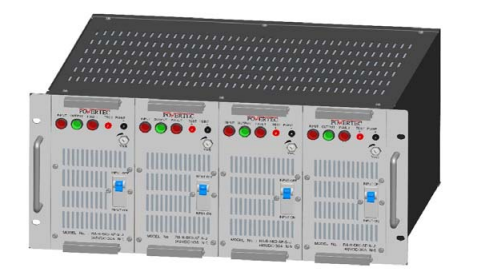
| LED Indications | Input OK (Red), Fault (Red), Output (Green) on each PIM. |
| Over-Voltage Protection | Protection operative at ≥58VDC |
| O/P Protection | Over-load, Short-circuit, Over-Voltage, Over-current, Over-temp protected. |
| O/P Voltage Adj. | ±3V adjustment provided on front panel for each PIM. |
| O/P Test Points | Provided on front panel for each PIM. |
| I/P ON/OFF MCB | Provided on front panel for each PIM. |
| Relay contact for each PIM | C to No (Open-Fault, Close-Ok) C to NC (close-Fault, Open-Ok) |
| Efficiency | >80% at full load (Exclusive OR-ing Diode power) |
| COLD-Swappable | Unit provided with Cold-swappable feature. |
| Vibration | 10 - 55Hz, 19.6m/s2 (2G) |
| Impact | 196.1m/s2 (10G), 11ms, Once each X, Y, & Z. |
| Agency Approvals | UL60950-1, C-UL (CSA60950-1), EN60950-1, EN50178 Complies with DEN-AN. |
| Conducted Noise | Complies with FCC-A, VCCI-A, CISPR22-A, EN55011, EN55022, 50081 |
| Harmonic Attenuator | Complies with IEC61000-3-2 class A. |
| Mounting | 19" Rack Mounting |
| Depth | 400mm |
| Width | 484mm |
| Height | 222.5mm (5U) |
| Weight (unpacked) | 20.0 Kg Approx. |
| Input and PFC | Screw Terminal |
| Output | Cu Buss bar |
| a) | Adjust the output voltage of each PIM to second place of decimal..(after switch-off of other PIMs). Monitor/confirm the output voltage on test points. |
| b) | Increase the load to 50% & note voltage, 100% and note output voltsabulate as desired. |
| c) | Ensure that the all PIM Voltages are closely matching with each other, and follow at 50% as well as 100% of nominal load |
| d) | Connect the BUSSBAR to load at Output terminals for operation. |


